Voltage Indicator
The voltage indicator (IN EŽ) is a set of devices for controlling a „Pantograph down“ signal sign depending on the position of high speed circuit breakers. This set of devices includes cable or wireless (radio transmittion) connection and a light indicator with the „Pantograph down“ sign, which has been approved by SŽDC.
The voltage indicator indicates the occurence of a voltage difference in electric sectioning. The information is then transferred by cables or a radio transmission to the „Pantograph down“ sign. If the signal sign is on, it indicates, that there can be a voltage difference in the electric line caused by a voltage-free state of one of the sections and, on the other hand, if the signal is off, it indicates that both sections of the electrical sectionning are under the same voltage. Dangerous voltage difference on sectioning in front of a substation occurs then only when a feeder determined for a respective track is switched on while the second feeder for the same track is switched off and a section insulator serving for a by-pass of electric sectioning of the track is switched off. If in such case IN-EŽ is not installed, it is necessary to pull down the pantograph at every electric sectioning at each substation and switching station..
IN EŽ is standardly delivered in wiring for a double track, i.e. the OCL is expected to be power supplied by 4 feeder high speed circuit breakers. In case of power supply of three and more tracks further driver is used. IN EŽ is energized from a DC part of 110 V DC (48 V DC) own consumption of a substation or a switching station.
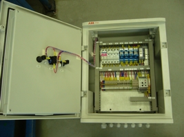
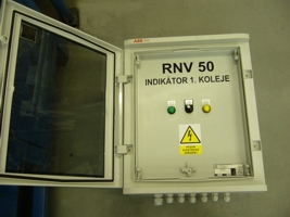
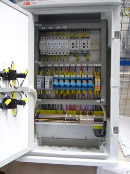
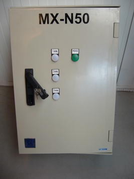
IN EŽ is mainly formed by a driver. The driver is a set of electrical devices enabling, apart of automatic control of the light signal sign „Pantograph down“ based on the evaluation of the voltage difference, also local, remote and central remote control from a dispatching centre. The set of electrical devices is placed in a plastic distribution board with IP 44/00 shileding.
The communication with the superior systems is performed by the means of protocols:
- EN 60870-5-101 (IEC 60870-5-101)
- EN 60870-5-104 (IEC 60870-5-104)
The driver’s technical parameters:
Material: plastic
Shielding: IP 44/00
Insulation Class: II
Mechanical resistance: IK 10
Operating temperature: -5°C ÷ +40°C
Colour: grey RAL7035
Rated permanent current: 3 A
Rated frequency: 50 – 60 Hz
Max. effected radiated power at 25°C: 77 W
Rated voltage – main circuits / auxiliar circuits:
2 – 110 V DC IT or 2 – 48 DC IT / 2 -24 V DC IT
Rated insulation voltage: 300 V
Dielectric AC withstand voltage: 2 kV
Impulse voltage: 4,5 kV
Standard: ČSN EN 60439-1 ed.2


